Transmission Lines
Impedance bridging is unsuitable for RF connections, because it causes power to be reflected back to the source from the boundary between the high and the low impedances. The reflection creates a standing wave if there is reflection at both ends of the transmission line, which leads to further power waste and may cause frequency-dependent loss. In these systems, impedance matching is desirable.
In electrical systems involving transmission lines (such as radio and fiber optics)—where the length of the line is long compared to the wavelength of the signal (the signal changes rapidly compared to the time it takes to travel from source to load)— the impedances at each end of the line must be matched to the transmission line's characteristic impedance to prevent reflections of the signal at the ends of the line. (When the length of the line is short compared to the wavelength, impedance mismatch is the basis of transmission-line impedance transformers; see previous section.) In radio-frequency (RF) systems, a common value for source and load impedances is 50 ohms. A typical RF load is a quarter-wave ground plane antenna (37 ohms with an ideal ground plane; it can be matched to 50 ohms by using a modified ground plane or a coaxial matching section, i.e., part or all the feeder of higher impedance).
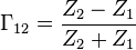
The general form of the voltage reflection coefficient for a wave moving from medium 1 to medium 2 is given by
while the voltage reflection coefficient for a wave moving from medium 2 to medium 1 is


so the reflection coefficient is the same (except for sign), no matter from which direction the wave approaches the boundary.
There is also a current reflection coefficient; it is the same as the voltage coefficient, except that it has an opposite sign. If the wave encounters an open at the load end, positive voltage and negative current pulses are transmitted back toward the source (negative current means the current is going the opposite direction). Thus, at each boundary there are four reflection coefficients (voltage and current on one side, and voltage and current on the other side). All four are the same, except that two are positive and two are negative. The voltage reflection coefficient and current reflection coefficient on the same side have opposite signs. Voltage reflection coefficients on opposite sides of the boundary have opposite signs.
Because they are all the same except for sign it is traditional to interpret the reflection coefficient as the voltage reflection coefficient (unless otherwise indicated). Either end (or both ends) of a transmission line can be a source or a load (or both), so there is no inherent preference for which side of the boundary is medium 1 and which side is medium 2. With a single transmission line it is customary to define the voltage reflection coefficient for a wave incident on the boundary from the transmission line side, regardless of whether a source or load is connected on the other side.
Read more about this topic: Impedance Matching
Famous quotes containing the word lines:
“There is something to be said for government by a great aristocracy which has furnished leaders to the nation in peace and war for generations; even a Democrat like myself must admit this. But there is absolutely nothing to be said for government by a plutocracy, for government by men very powerful in certain lines and gifted with the “money touch,” but with ideals which in their essence are merely those of so many glorified pawnbrokers.”
—Theodore Roosevelt (1858–1919)